Resistor Networks
September 26, 2016 While most audio signal processing is now done using digital circuitry, it's often easier in some cases to implement simple audio filters using venerable analog circuit techniques. While using an analog bandpass filter in a recent circuit design, I ran into the common problem of needing an uncommon resistance value to hit the desired frequency. I did what most electrical engineers do in that case, I used a parallel combination of two resistors. The problem could have been solved, also, by a series combination of two resistors. In my case, a parallel combination of a 470 k-ohm and a 1 meg-ohm resistor gave a resistance of 320 k-ohms, close enough to my desired 330 k-ohms. The formulas for calculating series and parallel resistance are found in the figure, below. | Resistors in series and parallel combination. In the series case, the resistance R is calculated as the sum of the individual resistances. In a parallel combination, the conductance, which is the reciprocal of the resistance, is summed. (Created using Inkscape.) |
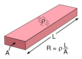
 | Resistance formula for a conductor with resistivity, ρ. (Illustration by the author using Inkscape.) |
 |
| Y-Delta resistor networks and their equivalent resistor values. (Created using Inkscape.) |
| RA = 996 | R1 = 1315 | ||
| RB = 2202 | R2 = 595 | ||
| RC = 4740 | R3 = 276 |
| Nodes | Resistance (calc) | Δ (meas) | Y (meas) | Error Δ (%) | Error Y (%) | |
| 1-2 | 1909.6 | 1909 | 1902 | 0.0 | -0.4 | |
| 2-3 | 871.0 | 871 | 873 | 0.0 | 0.2 | |
| 3-1 | 1591.2 | 1540 | 1590 | -3.2 | -0.1 |
 |
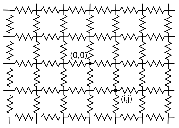
| An infinite lattice of resistors in two dimensions, connected at each crossing. The resistance between some of the nodes will give an experimental value of pi (π). (Illustration by the author using Inkscape.) |
| (i,j) | R | (i,j) | R | |
| 0,0 | 0 | || | 2,2 | (8/3π) |
| 0,1 | 1/2 | || | 3,3 | (46/15π) |
| 1,0 | 1/2 | || | 4,4 | (352/105π) |
| 1,1 | 2/π | || | 5,5 | (1126/315π) |
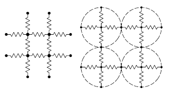
 | Modeling electrical conductivity in a rectangular array of particles. The model has resistive links to nearest neighbors. Fig. 1 of ref. 12, via arXiv |
References:
- A.E. Kennelly, "Equivalence of triangles and three-pointed stars in conducting networks", Electrical World and Engineer, vol. 34 (1899), pp. 413-414. An early tutorial can be found at Robert D. Evans, "Analytical Solutions," The Electrical Journal, vol. XVI, January-December, 1919, pp. 345-349 (via Google Books).
- D. Atkinson and F. J. van Steenwijk, "Infinite resistive lattices," Amer. Jour. Phys., vol. 67, no. 6 (June, 1999), pp. 486-492. A PDF copy can be found, here.
- N.Sh. Izmailian, and R. Kenna, "A generalised formulation of the Laplacian approach to resistor networks," arXiv, June 19, 2014.
- M. Owaidat, "On the uniform tiling with electrical resistors," arXiv, May 25, 2013.
- J. H. Asad, "Infinite Body Centered Cubic Network of Identical Resistors," Arxi, February 19, 2013.
- Jihad H. Asad, "Exact Evaluation of The Resistance in an Infinite Face-Centered Cubic Network," Arxiv, October 7, 2012.
- J. H. Asad, "Infinite Face Centered Cubic Network of Identical Resistors," Arxiv, May 5, 2012.
- Jozsef Cserti, Gabor Szechenyi and Gyula David, "Uniform tiling with electrical resistors," Arxiv, March 7, 2011.
- J. H. Asad, R. S. Hijjawi, A. J. Sakaji and J. M. Khalifeh, "Resistance Calculation for an infinite Simple Cubic Lattice- Application of Green's Function,", May 1,2009.
- J. H. Asad, A. J. Sakaji, R. S. Hijjawi and J. M. Khalifeh, "On the resistance of an Infinite Square Network of Identical Resistors- Theoretical and Experimental Comparison," arXiv, April 3, 2009.
- R. S. Hijjawi, J. H. Asad, A. J. Sakaji, M. Al-Sabayleh and J. M. Khalifeh, "Infinite Simple 3D Cubic Lattice of Identical Resistors (Two Missing Bonds)," arXiv, March 24, 2009.
- Yakov M. Strelniker, Shlomo Havlin, Richard Berkovits, and Aviad Frydman, "Resistance distribution in the hopping percolation model," arXiv, June 7, 2005.
- Thomas Lam, "Electrical Resistor Networks," Notices of the American Mathematical Society, vol. 63, no. 8 (September, 2016), pp. 875f., DOI: http://dx.doi.org/10.1090/noti1420 (PDF file).